Injection molded parts usually fail manufacturability review for simple reasons.
The mold cannot open in a direction that releases the part cleanly. Or the pull direction exists, but one or more faces do not have enough draft.
The problem is timing. These issues often surface during tooling trials or supplier DFM review, long after the CAD model has been treated as finished.
The Two Checks That Decide Moldability
For a molded part to release, two geometric questions need clear answers:
- What direction should the mold open?
- Does every relevant face release cleanly along that direction?
The first question is the pull direction problem. The second is the per-face draft problem.
Both are easy to describe and hard to check consistently by hand. A single hidden undercut or near-vertical face can turn into a tooling delay, even if the rest of the model looks clean.
Why Manual DFM Review Breaks Down
Traditional CAD review depends on expert inspection. A tooling engineer rotates the model, chooses an apparent opening direction, checks draft, and flags faces that look risky.
That workflow works when the part is simple, the reviewer is available, and the standards are obvious. It breaks down when teams move fast, parts get complex, or different customers enforce different draft thresholds.
The result is inconsistency. Two reviewers can choose different pull directions. Two customers can apply different standards. And the decision often happens after design intent has already been locked.
Odin Turns Moldability Into a Geometric Pipeline
Odin approaches the problem as a two-stage geometric analysis that runs directly on the CAD model. Instead of asking whether the part generally looks moldable, it produces auditable findings for the faces that matter.
The pipeline has two stages:
- Pull direction analysis computes the best mold-opening axis for a designer-selected Class A region.
- Per-face draft analysis evaluates every face against the customer's draft standards once the pull direction is known.
Stage 1: Find the Best Pull Direction
The designer starts by selecting the Class A region: the surfaces that must release cleanly. Each face contributes an outward-pointing direction and its surface area.
For any candidate pull direction, Odin computes a draft score for each face. A favorable face scores well. An undercut scores poorly. The goal is not to maximize the average score, because averages hide the face that will fail.
The right objective is stricter: find the direction that makes the worst face as good as possible.
This is a minimax problem on the unit sphere. If a valid axis exists, Odin returns the pull direction and the worst-case draft angle along it. If no valid axis exists, the system identifies the face that creates the true undercut.
The Globe Analogy
Picture every face normal as a point on a globe. The optimal pull direction is the center of the smallest cap that contains all of those points.
The size of that cap tells you the worst-case draft. If the cap has to grow beyond a hemisphere, the region contains an undercut that no pull direction can resolve.
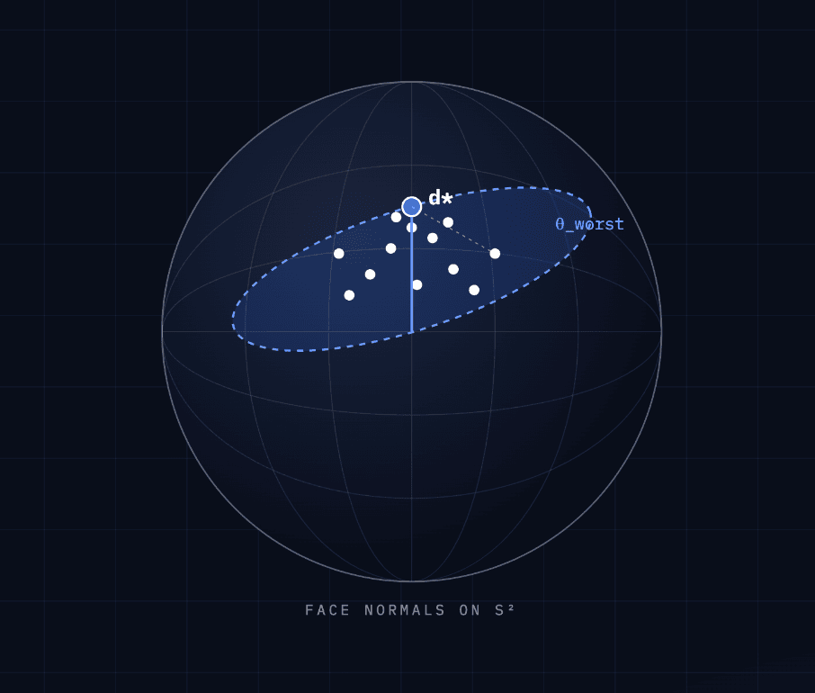
That is the important shift: Odin does not guess a pull direction and hope the part works. It searches for the weakest face and optimizes around it.
How the Search Stays Fast Enough for Designers
A brute-force search over every possible axis would be too expensive. Odin uses a staged search that keeps the result interactive.
- Start with an area-weighted average of face directions, so larger faces guide the initial estimate.
- Run a coarse search across 1,024 candidate directions around that starting guess.
- Run a fine search across 512 candidate directions within a narrow cone around the best coarse result.
The sampling uses a Fibonacci sphere pattern, which distributes candidates evenly across solid angle. That avoids the bias of naive latitude-longitude grids, where samples cluster near the poles and leave other regions sparse.
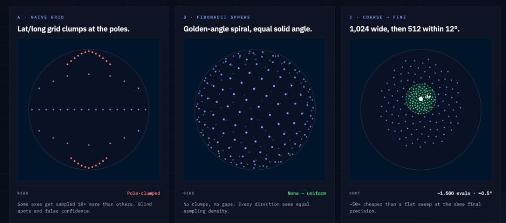
The final pull direction is within roughly 0.5 degrees of the true optimum. In a workflow where the downstream draft threshold may be 2.5 degrees, the limiting factor is the manufacturing standard, not the numerical method.
Stage 2: Evaluate Every Face Against the Right Standard
Once the pull direction is established, Odin evaluates each face in the part against the customer's standards library.
Each face receives three useful classifications:
- Passing, warning, or critical, based on thresholds drawn from the customer's live standards.
- Cavity-side or core-side, so tooling teams know which mold half the issue affects.
- Matched resolutions, so each flagged face is paired with remediation paths that fit its severity and location.
The Architecture Matters More Than the Check
At enterprise scale, the value is not just detecting bad draft. The value is separating geometry, standards, and remediation so each can evolve independently.
Odin separates the pipeline into three concerns:
- Geometric measurement: a single auditable number per face, computed from canonical CAD topology.
- Standards application: customer-specific thresholds pulled from a structured knowledge graph.
- Resolution matching: remediation options matched to severity, location, and manufacturing process.
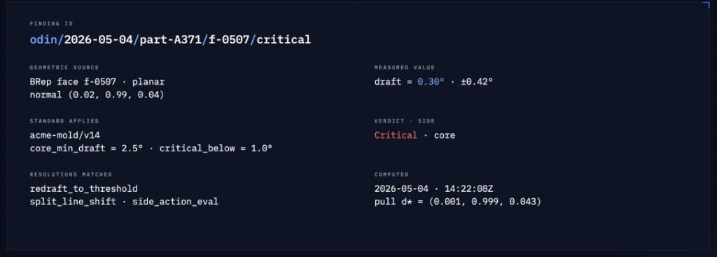
For example, a finding is not just "draft failed." It carries the geometric source, the measured draft value, the applied customer standard, the mold side, and the resolution paths that matched the failure.
That means the same geometry engine can serve a precision-optics customer and a structural-housing customer without a forked implementation or custom build.
Why True B-Rep Geometry Matters
Draft analysis should be computed on the geometry the CAD model actually contains, not on a mesh approximation of that geometry.
Meshes and tessellations can introduce artifacts: faceting, edge bias, and degenerate samples that make smooth surfaces look worse or better than they are. Odin works on true B-Rep geometry and uses sampling schemes designed to avoid edge bias and degenerate-surface contamination.
A pass should mean every face passed the relevant manufacturability requirement. Not most faces. Not the average face. Every face.
The Audit Trail Is the Product
A useful DFM finding needs more than a red highlight. It needs to explain what was checked, how it was measured, whose standard was applied, and what should happen next.
Odin records the measured value, the geometric source, the standard used for evaluation, the side of the mold affected, and the matched resolution paths.
That creates a defensible record for design, tooling, manufacturing, and quality teams. The finding is no longer a subjective note from a review meeting. It is a traceable decision tied to the CAD model and the customer's own standards.
Catching Draft Problems Before Tooling
Draft and undercut issues are not mysterious. They are geometric constraints that can be measured before tooling begins.
The hard part is making the check rigorous enough to trust, fast enough to run during design, and flexible enough to respect different customer standards.
Try Odin to catch pull direction, draft angle, and undercut issues before tooling:
Upload your CAD, pick the Class A surface, and Odin derives the pull direction, flags every draft and undercut issue, and gives your team a report they can act on before supplier review.
Try Odin Free →For more on the manufacturing problem this solves, read Draft Angles in Injection Molding.